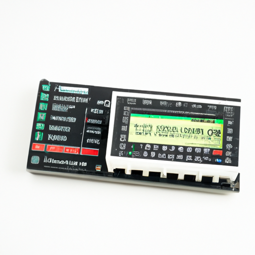
DSP digital signal processor is a processor composed of large-scale or very large-scale integrated circuit chips, which is used to complete a certain signal processing task. It is gradually developed to meet the needs of high-speed real-time signal processing tasks. With the development of integrated circuit technology and digital signal processing algorithm, the implementation method of digital signal processor is also changing, and the processing function is constantly improved and expanded.   Before the emergence of DSP digital signal processor chips, digital signal processing can only be completed by microprocessors. However, due to the slow processing speed of microprocessors, they can not meet the high-speed real-time requirements of increasing amount of information. Subsequently, the emergence of DSP chip meets these needs, and the application field has become extensive.   Digital signal processor is not only limited to the audio and video level, it is widely used in communication and information systems, signal and information processing, automatic control, radar, military, aerospace, medical, household appliances and many other fields.   In the past, general microprocessors were used to complete a large number of digital signal processing operations, which was slow and difficult to meet the actual needs; Using bit chip microprocessors and fast parallel multipliers at the same time was once an effective way to realize digital signal processing, but this method has many devices, complex logic design and program design, large power consumption and high price.   The emergence of digital signal processor solves the above problems well. DSP can quickly realize the signal acquisition, transformation, filtering, estimation, enhancement, compression, recognition and other processing, in order to get the signal form that meets people's needs.   Digital signal processor DSP enhances the performance and availability of the vehicle host, improves the audio and video quality, provides more flexibility and faster design cycle. With the development of technology, it is believed that more auditory and visual effects can be provided in the future, making the on-board host become a high-tech information and entertainment center in the car.
0
  Crystal oscillators can help electronic systems provide frequencies for synchronous operation, as frequency references or to achieve accurate timing.   In microprocessor-based systems, there are several different frequency signals used to execute instructions, move data into and out of memory, and external communication interfaces.   A simple embedded controller may have a clock frequency of several MHz, while microprocessors in personal computers usually expect an input frequency of 15 MHz. This will multiply internally to provide the frequency of the CPU and other subsystems. Other components in the system may have their own frequency requirements.   In addition to providing the basic requirements of the specified frequency, the oscillator may have to meet other requirements depending on the application requirements of the product.   For example, many product applications require extremely precisely defined frequencies. This is particularly important for systems that need to communicate with other devices through serial or wireless interfaces. Accuracy is usually measured in parts per million (PPM).   At the same time, the trimming circuit can be based on resistance capacitance (RC) or inductance capacitance (LC) networks. These devices are relatively simple and can change the frequency in a wide range. However, designing an accurate RC oscillator or LC oscillator requires the use of expensive precise components. Even so, they cannot meet the highest accuracy and stability required by many product applications.   Crystal oscillators (usually quartz) can also be used as resonant components. Cut the crystal into two parallel crystal planes and deposit metal contacts on them. Quartz has piezoelectric effect, which means that when the crystal is placed under pressure, voltage will be generated on its crystal surface. On the contrary, when voltage is applied to the crystal, the crystal will also change its shape.
0
  There are more than 1000 kinds of embedded processors in the world, and there are more than 30 series of popular architectures. Almost every semiconductor manufacturer now produces embedded processors.   The architecture of embedded microprocessor has experienced the transformation from CISC to RISC and compact RISC; The number of bits is from 4 bits, 8 bits, 16 bits, 32 bits to 64 bits; The addressing space is generally 64KB ~ 16MB, and the processing speed is 0.1mips ~ 2000mips; The commonly used package is 8 ~ 144 pins.   The design of embedded microprocessor is similar to that of ordinary desktop computer in basic principle microprocessor, but it has higher working stability, less power consumption, strong adaptability to the environment (such as temperature, humidity, electromagnetic field, vibration, etc.), smaller volume, and more integrated functions.   In terms of classification, embedded processors generally include microprocessors, microcontrollers, DSP processors, and systems on chip.   Micro processor unit (MPU) evolved from CPU in general-purpose computer. Its characteristic is that it has more than 32-bit processors, with high performance, of course, its price is also relatively high.   The typical representative of embedded microcontroller unit (MCU) is single chip microcomputer. Although it has been more than 20 years since the emergence of single chip microcomputer in the late 1970s, this 8-bit electronic device is still widely used in embedded devices.   Embedded digital signal processor (EDSP) is a processor specially used in signal processing. It has a special design in system structure and instruction algorithm, and has high compilation efficiency and instruction execution speed. DSP has been widely used in digital filtering, FFT, spectral analysis and other instruments.   Embedded system on chip: SOC pursues the integrated device with the largest tolerance of product system, which is one of the hot topics in the field of embedded applications. The biggest feature of SOC is the successful integration of software and hardware, which directly embeds the code module of the operating system in the processor chip.    
0
  With the rapid advancement of wireless communication technologies, RF directional couplers, as crucial microwave/millimeter-wave components, play an indispensable role in numerous fields such as wireless communication, radar, and satellite communication. This article delves into the main application scenarios of RF directional couplers to provide a more comprehensive and in-depth understanding for readers.   Basic Principles of RF Directional Couplers   RF directional couplers are microwave devices based on coupling structures. Their working principle can be briefly summarized as: Inputting the millimeter-wave signal to be tested and the calibration signal carrying the reference plane into a dual-channel RF directional coupler. One of the signals is input into a reverser, where it is reversed based on the reversal effect of the reverser. At this point, the two signals travel in opposite directions, forming a power overlay, resulting in a higher detection level. Then, the voltage ratio is used as the circuit output to achieve direction finding.   RF directional couplers have several key technical indicators, including directionality, standing wave ratio, coupling degree, and insertion loss. They can distribute microwave signals according to a certain ratio. Their basic structure is composed of transmission lines, which can be coaxial cables, rectangular waveguides, circular waveguides, strip lines, or microstrip lines, resulting in various types with significant differences. However, from the perspective of coupling mechanisms, they are mainly divided into four types: aperture coupling, parallel coupling, branch coupling, and matched double-T coupling.   Primary Application Scenarios of RF Directional Couplers   Wireless Communication In the field of wireless communication, RF directional couplers have extensive applications. Firstly, they can distribute antenna input signals to multiple transceivers, enabling multi-antenna systems and enhancing wireless communication coverage and connection speed. Secondly, RF directional couplers can combine output signals from multiple transceivers into a single output signal, further improving the stability and reliability of wireless communication. Additionally, they can be used for power monitoring, source output power stabilization, signal source isolation, and sweep testing of transmission and reflection, providing powerful support for the design and optimization of wireless communication systems.   Radar Systems RF directional couplers also play a crucial role in radar systems. They can achieve mutual coupling between multiple radar antennas, enhancing the detection accuracy and range of radar systems. By precisely controlling signal distribution and combination, RF directional couplers ensure efficient and accurate detection capabilities of radar systems in various complex environments. Additionally, they can be used for power monitoring and calibration of radar systems, ensuring optimal operational status.   Satellite Communication In the field of satellite communication, RF directional couplers have widespread applications as well. They can be used for signal distribution and combination in satellite communication systems, enhancing coverage and transmission efficiency. Simultaneously, they can monitor and calibrate power in satellite communication systems, ensuring stable communication quality under various complex environments. Furthermore, with the continuous development of satellite communication technologies, the application of RF directional couplers in satellite internet, satellite navigation, and other fields will become increasingly extensive.   Other Fields In addition to the above fields, RF directional couplers also have extensive applications in other areas. For instance, in automotive radar, the Internet of Things (IoT), and 5G cellular radio frequency (RF) applications, RF directional couplers can be used to monitor and control RF power levels without causing losses in transmission lines and loads. Additionally, they can be employed for output signal monitoring of high-power transmitters, avoiding potential damage to sensitive instruments from high signal levels.   III. Conclusion   In conclusion, as crucial microwave/millimeter-wave components, RF directional couplers have extensive applications in numerous fields such as wireless communication, radar, and satellite communication. By precisely controlling signal distribution and combination, RF directional couplers provide stable and efficient performance guarantees for equipment and systems in these fields. With the continuous development of communication technologies, the application prospects of RF directional couplers will become even broader.
0
Panasonic Industrial Automation Sales
Analog Devices Inc.
Susumu
Ohmite
Maxim Integrated
Vishay Dale
Rohm Semiconductor
Bourns Inc.
CTS Resistor Products
Vishay Foil Resistors (Division of Vishay Precision Group)
YAGEO
Vishay Foil Resistors (Division of Vishay Precision Group)
Stackpole Electronics Inc
Samsung Electro-Mechanics
Vishay Beyschlag/Draloric/BC Components
TE Connectivity Passive Product
MEMS OSC VCXO 491.5200MHZ LVPECL
MEMS OSC VCXO 491.5200MHZ LVDS
MEMS OSC VCXO 345.6000MHZ LVPECL
MEMS OSC VCXO 644.53125MHZ LVDS
MEMS OSC VCXO 245.7600MHZ LVDS
MEMS OSC VCXO 491.5200MHZ LVDS
MEMS OSC VCXO 625.0000MHZ HCSL
MEMS OSC VCXO 307.695484MHZ LVDS

+86-15816200391

点击这里给我发消息
0