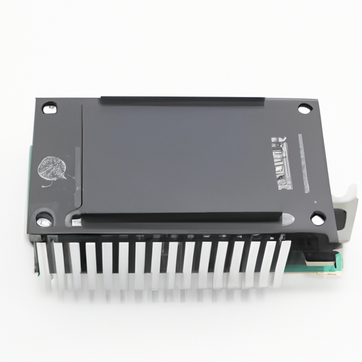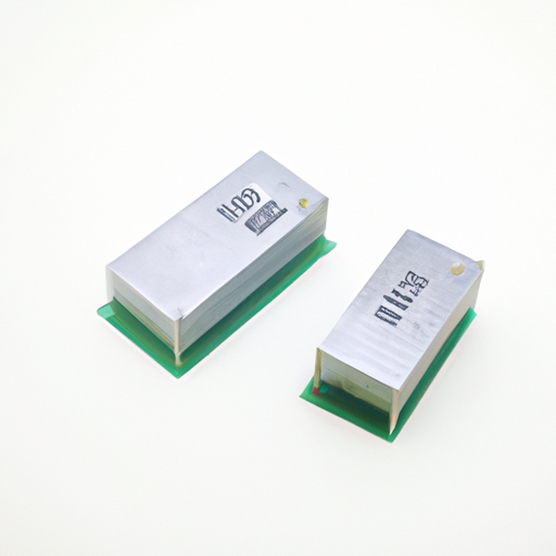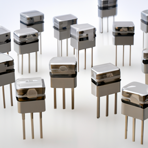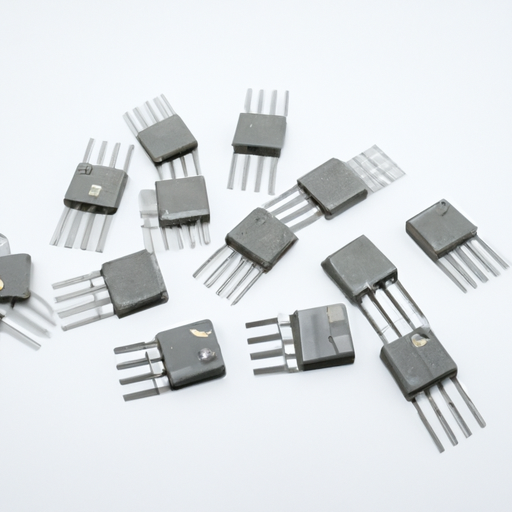
Application Development in Wireless Charging Coils for MM74HC373N: Key Technologies and Success StoriesWireless charging technology has become increasingly popular, driven by the demand for convenience in charging portable devices such as smartphones, electric vehicles (EVs), and wearables. The MM74HC373N, a high-speed CMOS octal latch, can play a significant role in the development of wireless charging systems. This overview highlights key technologies in wireless charging coils and showcases success stories that illustrate the application of these technologies, particularly in conjunction with components like the MM74HC373N.
Key Technologies in Wireless Charging Coils1. Resonant Inductive Coupling2. Magnetic Resonance3. Capacitive Coupling4. Control and Communication Protocols5. Power Management ICs1. Smartphone Manufacturers2. Electric Vehicles (EVs)3. Consumer Electronics4. Wearable Technology5. Healthcare Devices Role of MM74HC373N in Wireless Charging ApplicationsThe MM74HC373N can significantly enhance the functionality of wireless charging systems through: Data Latching: It can latch control signals that manage the charging system's operation, such as detecting the presence of a device and enabling or disabling charging accordingly.Data Latching: It can latch control signals that manage the charging system's operation, such as detecting the presence of a device and enabling or disabling charging accordingly.Signal Processing: The MM74HC373N can process signals from the charging pad to monitor the charging status, ensuring efficient power transfer and preventing overcharging.Signal Processing: The MM74HC373N can process signals from the charging pad to monitor the charging status, ensuring efficient power transfer and preventing overcharging.Integration with Microcontrollers: It can interface with microcontrollers to provide a robust control mechanism, allowing for advanced features like dynamic power adjustment based on the device's needs.Integration with Microcontrollers: It can interface with microcontrollers to provide a robust control mechanism, allowing for advanced features like dynamic power adjustment based on the device's needs. Success Stories ConclusionThe integration of technologies like the MM74HC373N in wireless charging systems enhances the efficiency, reliability, and user experience of power transfer. As wireless charging technology continues to evolve, the combination of innovative coil designs, advanced control mechanisms, and standardized protocols will drive further adoption across various industries. The success stories from smartphones to electric vehicles illustrate the potential and versatility of wireless charging technology, paving the way for a future where charging is more convenient and accessible.

Application Development in Arrays and Signal Transformers for CFR-25JB-52-1M2: Key Technologies and Success StoriesApplication development in arrays and signal transformers, particularly for components like the CFR-25JB-52-1M2, requires a deep understanding of both the technical specifications of the component and its applications across various industries. Below, I will outline key technologies, potential applications, and success stories related to this area.
Key Technologies1. Signal Transformation2. Array Technology3. Embedded Systems4. Simulation and Modeling5. IoT Integration1. Telecommunications2. Medical Devices3. Industrial Automation4. Consumer Electronics5. Automotive Systems1. Telecom Infrastructure2. Medical Imaging3. Smart Home Devices4. Automotive Safety Systems Applications Success Stories ConclusionThe development of applications using arrays and signal transformers like the CFR-25JB-52-1M2 is a dynamic field with numerous opportunities across various industries. By leveraging key technologies and learning from successful implementations, developers can create innovative solutions that enhance performance, reliability, and user experience. As technology continues to evolve, the integration of these components will likely play an increasingly critical role in the advancement of electronic systems, paving the way for future innovations in telecommunications, healthcare, automotive, and consumer electronics.

Application Development in Fixed Inductors for MM74HC374N: Key Technologies and Success StoriesThe MM74HC374N is a high-speed CMOS octal D-type flip-flop with a 3-state output, widely utilized in digital circuits for data storage and transfer. The integration of fixed inductors in circuits utilizing the MM74HC374N enhances performance, efficiency, and reliability. Below, we explore key technologies and notable success stories that illustrate the effective application of fixed inductors in conjunction with this component.
Key Technologies1. High-Frequency Inductors2. Integrated Circuit Design3. Power Management4. RF Applications5. Simulation and Modeling1. Consumer Electronics2. Automotive Applications3. Industrial Automation4. Telecommunications5. IoT Devices Success Stories ConclusionThe integration of fixed inductors with the MM74HC374N has led to significant advancements across various fields, including consumer electronics, automotive, industrial automation, telecommunications, and IoT. By leveraging key technologies such as high-frequency inductors, power management techniques, and advanced circuit design, developers can create efficient and reliable systems that meet the demands of modern applications. The success stories across these industries underscore the importance of this integration in achieving performance and reliability in electronic designs, paving the way for future innovations.
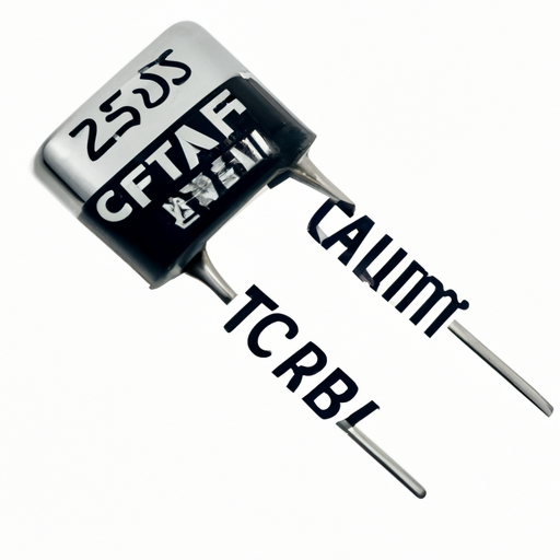
Overview of Tantalum-Polymer Capacitors: CFR-25JB-52-1K2Tantalum-polymer capacitors, such as the CFR-25JB-52-1K2, are advanced electronic components that leverage the unique properties of tantalum and conductive polymers. This combination results in capacitors that are not only compact but also highly efficient and reliable, making them suitable for a wide range of applications.
Core Functional Technology1. Construction2. High Capacitance and Voltage Ratings3. Low ESR (Equivalent Series Resistance)4. Temperature Stability5. Reliability1. Consumer Electronics2. Automotive Applications3. Industrial Equipment4. Telecommunications5. Medical Devices Key FeaturesCompact Size: Their small footprint allows for integration into space-constrained designs, such as portable electronics.Compact Size: Their small footprint allows for integration into space-constrained designs, such as portable electronics.High Ripple Current Handling: Capable of managing high ripple currents, making them ideal for power supply applications.High Ripple Current Handling: Capable of managing high ripple currents, making them ideal for power supply applications.Low Leakage Current: Essential for battery-operated devices, helping to extend battery life and improve efficiency.Low Leakage Current: Essential for battery-operated devices, helping to extend battery life and improve efficiency.Wide Range of Capacitance Values: Available in various capacitance values to cater to diverse application requirements.Wide Range of Capacitance Values: Available in various capacitance values to cater to diverse application requirements. Application Development Cases ConclusionThe CFR-25JB-52-1K2 tantalum-polymer capacitor exemplifies the advancements in capacitor technology, offering a blend of high performance, reliability, and compactness. Its applications span various industries, including consumer electronics, automotive, industrial, telecommunications, and medical devices. As technology continues to evolve, the demand for such capacitors is expected to grow, driving further innovation and development in this field. Engineers and designers can leverage the unique properties of tantalum-polymer capacitors to enhance the performance and efficiency of their products, ensuring they meet the ever-increasing demands of modern applications.

Application Development in Aluminum-Polymer Capacitors for CFR-50JB-52-1K2: Key Technologies and Success StoriesAluminum-polymer capacitors, such as the CFR-50JB-52-1K2, are increasingly recognized for their superior performance characteristics, including high capacitance, low equivalent series resistance (ESR), and excellent thermal stability. These attributes make them suitable for a wide range of applications across various industries. Below, we explore key technologies that have facilitated their development and highlight notable success stories that demonstrate their impact.
Key Technologies1. Electrolyte Formulation2. Anode and Cathode Materials3. Manufacturing Techniques4. Thermal Management5. Simulation and Modeling1. Consumer Electronics2. Automotive Applications3. Renewable Energy Systems4. Industrial Automation5. Telecommunications Success Stories ConclusionThe advancements in aluminum-polymer capacitors, exemplified by the CFR-50JB-52-1K2, are a result of significant progress in materials science, manufacturing techniques, and thermal management solutions. Their successful application across diverse industries—ranging from consumer electronics to automotive, renewable energy, industrial automation, and telecommunications—underscores their versatility and critical role in modern electronic systems. As technology continues to evolve, the demand for high-performance capacitors is expected to grow, paving the way for further innovations in this dynamic field.
Core Functional Technologies of Silicon Capacitors1. Silicon-Based Dielectric Material2. High Voltage and Temperature Tolerance3. Low Equivalent Series Resistance (ESR)4. Integration with Silicon ICs5. Scalability1. Consumer Electronics2. Automotive Applications3. Telecommunications4. Medical Devices5. Industrial Automation Application Development Cases ConclusionSilicon capacitors, such as the CFR-50JB-52-1R2, represent a significant leap in capacitor technology, offering advantages in size, efficiency, and performance. Their diverse applications across consumer electronics, automotive, telecommunications, medical devices, and industrial automation highlight their versatility and effectiveness in modern electronic systems. As technology advances, silicon capacitors are poised to play an increasingly vital role in the development of next-generation electronic devices, driving innovation and enhancing performance across various industries.
Application Development in Niobium Oxide Capacitors for MM74HC393N: Key Technologies and Success StoriesNiobium oxide capacitors are emerging as a vital component in modern electronic applications, particularly in conjunction with integrated circuits like the MM74HC393N, a dual 4-bit binary ripple counter. Their unique properties enhance the performance and reliability of electronic systems across various industries. Below, we explore the key technologies that underpin the use of niobium oxide capacitors and highlight notable success stories that illustrate their impact.
Key Technologies1. High Dielectric Constant 2. Temperature Stability 3. Low Leakage Current 4. Integration with CMOS Technology 5. Reliability and Longevity 6. Advanced Manufacturing Techniques 1. Consumer Electronics 2. Automotive Applications 3. Telecommunications 4. Industrial Automation 5. Medical Devices Success Stories ConclusionThe integration of niobium oxide capacitors with integrated circuits like the MM74HC393N marks a significant advancement in electronic design. Their high capacitance, low leakage, and temperature stability make them suitable for a diverse range of applications across various industries. As technology continues to evolve, the role of niobium oxide capacitors is expected to expand, paving the way for innovative solutions in electronic design and application development. The success stories across consumer electronics, automotive, telecommunications, industrial automation, and medical devices underscore the transformative potential of these capacitors in enhancing performance and reliability in modern electronic systems.
Application Development in Film Capacitors for CFR-25JB-52-1K1: Key Technologies and Success StoriesFilm capacitors, such as the CFR-25JB-52-1K1, are integral components in a wide range of applications due to their reliability, stability, and superior performance characteristics. Below, we explore key technologies that have advanced the development of these capacitors, along with notable success stories that illustrate their impact across various industries.
Key Technologies1. Material Innovations2. Advanced Manufacturing Techniques3. Self-Healing Technology4. High-Temperature and High-Voltage Applications5. Simulation and Modeling1. Renewable Energy Systems2. Electric Vehicles (EVs)3. Consumer Electronics4. Industrial Automation5. Telecommunications Success Stories ConclusionThe application development of film capacitors like the CFR-25JB-52-1K1 is propelled by advancements in materials, manufacturing techniques, and a strong emphasis on reliability and performance. Success stories across diverse industries underscore the versatility and significance of film capacitors in contemporary technology, particularly in renewable energy, electric vehicles, and high-performance electronics. As technology continues to advance, film capacitors are poised to play an even more pivotal role in future innovations, driving efficiency and performance across various applications.
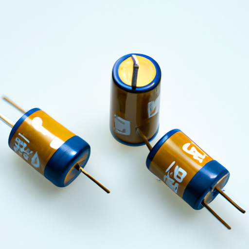
Electric Double Layer Capacitors (EDLCs) and Supercapacitors: Core Technologies and ApplicationsElectric Double Layer Capacitors (EDLCs), commonly referred to as supercapacitors, are pivotal in the energy storage sector, bridging the gap between traditional capacitors and batteries. Their unique characteristics enable them to store substantial amounts of energy and deliver it rapidly, making them suitable for a diverse array of applications. Below, we delve into the core functional technologies of EDLCs and highlight notable application development cases.
Core Functional Technologies of EDLCs1. Electrochemical Double Layer Formation2. High Surface Area Electrodes3. Electrolyte Types4. Hybrid Capacitors5. Energy and Power Density1. Electric Vehicles (EVs)2. Renewable Energy Systems3. Consumer Electronics4. Industrial Applications5. Smart Grids6. Wearable Technology Application Development Cases ConclusionElectric Double Layer Capacitors (EDLCs), or supercapacitors, represent a versatile and rapidly evolving technology in the energy storage landscape. Their unique characteristics enable them to serve a wide range of applications, from electric vehicles to renewable energy systems and consumer electronics. As research continues to advance in materials and design, the potential for EDLCs to play a critical role in future energy solutions is significant, paving the way for more efficient and sustainable energy systems.
The Evolution of Renewable Energy: A Path Towards a Sustainable Future I. IntroductionAs the world grapples with the pressing challenges of climate change, the importance of renewable energy has never been more pronounced. Renewable energy refers to energy derived from natural sources that are replenished at a faster rate than they are consumed. This includes solar, wind, hydro, biomass, and geothermal energy. The transition to renewable energy is crucial in reducing greenhouse gas emissions, promoting energy security, and fostering sustainable economic growth. In this article, we will explore the historical context of energy sources, the various types of renewable energy, the role of technology, economic implications, global perspectives, future trends, and ultimately, the path towards a sustainable future. II. Historical Context of Energy Sources A. Traditional Energy Sources: Fossil Fuels and Their ImpactFor centuries, fossil fuels—coal, oil, and natural gas—have been the backbone of global energy consumption. The Industrial Revolution marked a significant increase in fossil fuel usage, leading to unprecedented economic growth. However, this reliance on fossil fuels has come at a steep environmental cost. The burning of fossil fuels releases carbon dioxide and other greenhouse gases into the atmosphere, contributing to global warming and climate change. Additionally, the extraction and transportation of fossil fuels have led to environmental degradation, oil spills, and air and water pollution. B. The Emergence of Renewable EnergyIn response to the environmental consequences of fossil fuel consumption, renewable energy began to gain traction in the late 20th century. Early uses of renewable energy can be traced back to ancient civilizations that harnessed wind and water for power. However, it was not until the 1970s energy crisis that significant investments were made in renewable technologies. Technological advancements, such as the development of more efficient solar panels and wind turbines, have paved the way for modern renewable energy solutions. III. Types of Renewable Energy A. Solar EnergySolar energy is harnessed from the sun's rays using photovoltaic (PV) cells, which convert sunlight into electricity. The benefits of solar energy are numerous: it is abundant, sustainable, and produces no emissions during operation. However, challenges remain, including the high initial costs of installation and the need for energy storage solutions to manage supply and demand. B. Wind EnergyWind energy is generated by converting the kinetic energy of wind into electricity using wind turbines. Wind farms can be located onshore or offshore, with offshore wind farms often producing more energy due to stronger and more consistent winds. While wind energy is one of the fastest-growing renewable energy sources, it faces challenges such as noise pollution, impact on wildlife, and the need for suitable locations. C. HydropowerHydropower is generated by harnessing the energy of flowing water, typically through dams. It is one of the oldest and most widely used forms of renewable energy. Hydropower is highly efficient and can provide a stable energy supply. However, it also raises environmental concerns, such as the disruption of aquatic ecosystems and the displacement of communities. D. Biomass and BiofuelsBiomass refers to organic materials, such as plant and animal waste, that can be converted into energy. Biofuels, derived from biomass, can be used as alternatives to gasoline and diesel. While biomass can help reduce waste and provide a renewable energy source, its sustainability depends on responsible sourcing and land use practices. E. Geothermal EnergyGeothermal energy is derived from the heat stored beneath the Earth's surface. It can be harnessed for electricity generation or direct heating applications. Geothermal energy is reliable and has a small land footprint, but its availability is geographically limited, and the initial costs for drilling and infrastructure can be high. IV. The Role of Technology in Renewable EnergyTechnological innovations play a crucial role in the advancement of renewable energy. Energy storage technologies, such as lithium-ion batteries, are essential for managing the intermittent nature of solar and wind energy. Smart grid technology enhances energy distribution and efficiency, allowing for better integration of renewable sources into the existing grid. Additionally, artificial intelligence and data analytics are being utilized to optimize energy use, predict demand, and improve system reliability. V. Economic Implications of Renewable EnergyThe transition to renewable energy has significant economic implications. The renewable energy sector has become a major source of job creation, with millions of jobs in manufacturing, installation, and maintenance. Furthermore, the cost of renewable energy technologies has decreased dramatically over the past decade, making them increasingly competitive with fossil fuels. Government policies and incentives, such as tax credits and subsidies, have also played a vital role in promoting renewable energy adoption. VI. Global Perspectives on Renewable Energy A. Case Studies of Countries Leading in Renewable Energy AdoptionSeveral countries have emerged as leaders in renewable energy adoption. Germany's Energiewende (Energy Transition) initiative aims to transition the country to a sustainable energy system, with a focus on increasing the share of renewables in the energy mix. China has made significant investments in solar and wind energy, becoming the world's largest producer of solar panels and wind turbines. The United States has also made strides in renewable energy, with various states implementing ambitious renewable energy targets. B. Challenges Faced by Developing Countries in Adopting Renewable EnergyWhile many developed countries are making progress in renewable energy adoption, developing countries face unique challenges. Limited access to financing, inadequate infrastructure, and political instability can hinder the deployment of renewable technologies. However, international cooperation and investment can help overcome these barriers and promote sustainable energy solutions in developing regions. VII. Future Trends in Renewable EnergyThe future of renewable energy looks promising, with predictions indicating continued growth in the sector. International agreements, such as the Paris Agreement, emphasize the need for countries to reduce greenhouse gas emissions and transition to cleaner energy sources. Innovations on the horizon, such as floating solar farms and advanced nuclear technologies, hold the potential to further diversify the energy landscape and enhance sustainability. VIII. ConclusionThe transition to renewable energy is not just an environmental imperative; it is a pathway towards a sustainable future. As we face the challenges of climate change, energy security, and economic inequality, embracing renewable energy sources is essential. Individuals, businesses, and governments must work together to promote the adoption of renewable technologies, invest in research and development, and create policies that support a sustainable energy future. By doing so, we can envision a world powered by clean, renewable energy, ensuring a healthier planet for generations to come. IX. References1. International Renewable Energy Agency (IRENA). (2021). Renewable Power Generation Costs in 2020.2. U.S. Department of Energy. (2020). 2020 Wind Technologies Market Report.3. World Bank. (2021). The World Bank Group’s Energy Sector Strategy.4. United Nations. (2015). Paris Agreement.5. German Federal Ministry for Economic Affairs and Energy. (2020). The Energiewende: A Guide to the Energy Transition in Germany. This article provides a comprehensive overview of the evolution of renewable energy, highlighting its importance, challenges, and future potential in creating a sustainable world. The Evolution of Renewable Energy: A Path Towards a Sustainable Future I. IntroductionAs the world grapples with the pressing challenges of climate change, the importance of renewable energy has never been more pronounced. Renewable energy refers to energy derived from natural sources that are replenished at a faster rate than they are consumed. This includes solar, wind, hydro, biomass, and geothermal energy. The transition to renewable energy is crucial in reducing greenhouse gas emissions, promoting energy security, and fostering sustainable economic growth. In this article, we will explore the historical context of energy sources, the various types of renewable energy, the role of technology, economic implications, global perspectives, future trends, and ultimately, the path towards a sustainable future. II. Historical Context of Energy Sources A. Traditional Energy Sources: Fossil Fuels and Their ImpactFor centuries, fossil fuels—coal, oil, and natural gas—have been the backbone of global energy consumption. The Industrial Revolution marked a significant increase in fossil fuel usage, leading to unprecedented economic growth. However, this reliance on fossil fuels has come at a steep environmental cost. The burning of fossil fuels releases carbon dioxide and other greenhouse gases into the atmosphere, contributing to global warming and climate change. Additionally, the extraction and transportation of fossil fuels have led to environmental degradation, oil spills, and air and water pollution. B. The Emergence of Renewable EnergyIn response to the environmental consequences of fossil fuel consumption, renewable energy began to gain traction in the late 20th century. Early uses of renewable energy can be traced back to ancient civilizations that harnessed wind and water for power. However, it was not until the 1970s energy crisis that significant investments were made in renewable technologies. Technological advancements, such as the development of more efficient solar panels and wind turbines, have paved the way for modern renewable energy solutions. III. Types of Renewable Energy A. Solar EnergySolar energy is harnessed from the sun's rays using photovoltaic (PV) cells, which convert sunlight into electricity. The benefits of solar energy are numerous: it is abundant, sustainable, and produces no emissions during operation. However, challenges remain, including the high initial costs of installation and the need for energy storage solutions to manage supply and demand. B. Wind EnergyWind energy is generated by converting the kinetic energy of wind into electricity using wind turbines. Wind farms can be located onshore or offshore, with offshore wind farms often producing more energy due to stronger and more consistent winds. While wind energy is one of the fastest-growing renewable energy sources, it faces challenges such as noise pollution, impact on wildlife, and the need for suitable locations. C. HydropowerHydropower is generated by harnessing the energy of flowing water, typically through dams. It is one of the oldest and most widely used forms of renewable energy. Hydropower is highly efficient and can provide a stable energy supply. However, it also raises environmental concerns, such as the disruption of aquatic ecosystems and the displacement of communities. D. Biomass and BiofuelsBiomass refers to organic materials, such as plant and animal waste, that can be converted into energy. Biofuels, derived from biomass, can be used as alternatives to gasoline and diesel. While biomass can help reduce waste and provide a renewable energy source, its sustainability depends on responsible sourcing and land use practices. E. Geothermal EnergyGeothermal energy is derived from the heat stored beneath the Earth's surface. It can be harnessed for electricity generation or direct heating applications. Geothermal energy is reliable and has a small land footprint, but its availability is geographically limited, and the initial costs for drilling and infrastructure can be high. IV. The Role of Technology in Renewable EnergyTechnological innovations play a crucial role in the advancement of renewable energy. Energy storage technologies, such as lithium-ion batteries, are essential for managing the intermittent nature of solar and wind energy. Smart grid technology enhances energy distribution and efficiency, allowing for better integration of renewable sources into the existing grid. Additionally, artificial intelligence and data analytics are being utilized to optimize energy use, predict demand, and improve system reliability. V. Economic Implications of Renewable EnergyThe transition to renewable energy has significant economic implications. The renewable energy sector has become a major source of job creation, with millions of jobs in manufacturing, installation, and maintenance. Furthermore, the cost of renewable energy technologies has decreased dramatically over the past decade, making them increasingly competitive with fossil fuels. Government policies and incentives, such as tax credits and subsidies, have also played a vital role in promoting renewable energy adoption. VI. Global Perspectives on Renewable Energy A. Case Studies of Countries Leading in Renewable Energy AdoptionSeveral countries have emerged as leaders in renewable energy adoption. Germany's Energiewende (Energy Transition) initiative aims to transition the country to a sustainable energy system, with a focus on increasing the share of renewables in the energy mix. China has made significant investments in solar and wind energy, becoming the world's largest producer of solar panels and wind turbines. The United States has also made strides in renewable energy, with various states implementing ambitious renewable energy targets. B. Challenges Faced by Developing Countries in Adopting Renewable EnergyWhile many developed countries are making progress in renewable energy adoption, developing countries face unique challenges. Limited access to financing, inadequate infrastructure, and political instability can hinder the deployment of renewable technologies. However, international cooperation and investment can help overcome these barriers and promote sustainable energy solutions in developing regions. VII. Future Trends in Renewable EnergyThe future of renewable energy looks promising, with predictions indicating continued growth in the sector. International agreements, such as the Paris Agreement, emphasize the need for countries to reduce greenhouse gas emissions and transition to cleaner energy sources. Innovations on the horizon, such as floating solar farms and advanced nuclear technologies, hold the potential to further diversify the energy landscape and enhance sustainability. VIII. ConclusionThe transition to renewable energy is not just an environmental imperative; it is a pathway towards a sustainable future. As we face the challenges of climate change, energy security, and economic inequality, embracing renewable energy sources is essential. Individuals, businesses, and governments must work together to promote the adoption of renewable technologies, invest in research and development, and create policies that support a sustainable energy future. By doing so, we can envision a world powered by clean, renewable energy, ensuring a healthier planet for generations to come. IX. References1. International Renewable Energy Agency (IRENA). (2021). Renewable Power Generation Costs in 2020.2. U.S. Department of Energy. (2020). 2020 Wind Technologies Market Report.3. World Bank. (2021). The World Bank Group’s Energy Sector Strategy.4. United Nations. (2015). Paris Agreement.5. German Federal Ministry for Economic Affairs and Energy. (2020). The Energiewende: A Guide to the Energy Transition in Germany. This article provides a comprehensive overview of the evolution of renewable energy, highlighting its importance, challenges, and future potential in creating a sustainable world.
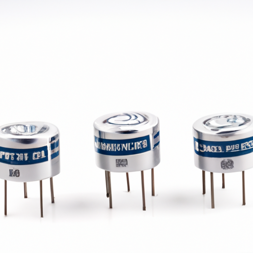
Tantalum Capacitors: Core Functional Technologies and Application Development CasesTantalum capacitors, including models like the CFR-50JB-52-1R1, are integral components in modern electronic devices due to their unique characteristics. Below, we delve into the core functional technologies that define their effectiveness and explore various application development cases that showcase their utility across different sectors.
Core Functional Technologies1. High Capacitance Density2. Voltage Stability3. Temperature Stability4. Low ESR (Equivalent Series Resistance)5. Long Lifespan and Reliability1. Consumer Electronics2. Automotive Electronics3. Medical Devices4. Telecommunications5. Industrial Automation Application Development Cases ConclusionTantalum capacitors, exemplified by the CFR-50JB-52-1R1 model, are indispensable in contemporary electronics due to their unique properties and capabilities. Their high capacitance density, voltage and temperature stability, low ESR, and reliability make them suitable for a diverse array of applications, from consumer electronics to automotive and medical devices. As technology continues to advance, the demand for tantalum capacitors is expected to rise, fostering further innovation and application development in this critical field.
Overview of CFR-25JB-52-1R Capacitor Networks and ArraysThe CFR-25JB-52-1R is a specific type of capacitor network that exemplifies the essential role of capacitor arrays in electronic applications. These components are designed to provide multiple capacitance values in a single package, which can simplify circuit design and improve performance. Below, we delve deeper into the core functional technologies, relevant articles, and application development cases that highlight the effectiveness of capacitor networks and arrays like the CFR-25JB-52-1R.
Core Functional Technologies1. Decoupling and Bypass Capacitors2. Filtering Applications3. Timing Circuits4. Energy Storage5. Voltage Regulation1. "Understanding Capacitor Networks"2. "The Role of Capacitors in Power Supply Design"3. "Capacitor Selection for RF Applications"4. "Designing Effective Filter Circuits with Capacitor Arrays"5. "Capacitor Networks in Timing Applications"1. Consumer Electronics2. Automotive Electronics3. Telecommunications4. Medical Devices5. Industrial Automation Articles and Resources Application Development Cases ConclusionCapacitor networks and arrays, such as the CFR-25JB-52-1R, are indispensable components in the design and operation of modern electronic systems. Their ability to manage power, filter signals, and stabilize voltage levels makes them critical in a wide range of applications, from consumer electronics to industrial automation. By understanding the core technologies and exploring practical case studies, engineers can leverage these components to create more effective and reliable electronic designs. As technology advances, the significance of capacitor networks will continue to grow, underscoring the need for ongoing research and development in this area.
Application Development in Specialized Resistors for CFR-25JB-52-1M: Key Technologies and Success StoriesThe CFR-25JB-52-1M is a prominent member of the CFR series of thick film resistors produced by Vishay. These resistors are celebrated for their reliability, precision, and adaptability across a wide range of applications. Below, we delve into the key technologies that underpin the development of specialized resistors like the CFR-25JB-52-1M, as well as notable success stories that illustrate their impact in various industries.
Key Technologies1. Thick Film Technology 2. Automated Manufacturing Processes 3. Material Science Innovations 4. Surface Mount Technology (SMT) 5. Environmental and Thermal Management 6. Simulation and Modeling Tools 1. Consumer Electronics 2. Automotive Applications 3. Medical Devices 4. Industrial Automation 5. Telecommunications Success Stories ConclusionThe CFR-25JB-52-1M resistor exemplifies the advancements in resistor technology and its diverse applications across various industries. By leveraging thick film technology, automated manufacturing, and material innovations, manufacturers can produce high-quality resistors that meet the rigorous demands of contemporary electronic applications. The success stories spanning consumer electronics, automotive, medical devices, industrial automation, and telecommunications underscore the versatility and reliability of specialized resistors in real-world applications, paving the way for future innovations in electronic design and manufacturing.
Application Development in Through-Hole Resistors for MM74HC4049N: Key Technologies and Success StoriesThe MM74HC4049N is a versatile hex inverter buffer/driver that plays a crucial role in various electronic applications, including interfacing, signal conditioning, and load driving. When integrated with through-hole resistors, it enhances circuit performance and reliability. Below, we explore key technologies and notable success stories that illustrate the effective use of this combination.
Key Technologies1. Through-Hole Resistor Technology2. PCB Design3. Signal Conditioning4. Power Management5. Prototyping and Testing1. Consumer Electronics2. Industrial Automation3. Educational Kits4. DIY Projects5. Robotics Success Stories ConclusionThe integration of the MM74HC4049N with through-hole resistors provides a robust platform for a wide array of applications. By leveraging key technologies such as PCB design, signal conditioning, and power management, developers can create effective and reliable solutions. The success stories across various industries underscore the practical applications and advantages of this combination, solidifying its status as a staple in both professional and hobbyist electronics. As technology continues to evolve, the enduring relevance of the MM74HC4049N and through-hole resistors will likely inspire further innovation and development in electronic design.
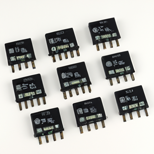
Overview of Resistor Networks and ArraysResistor networks and arrays, such as the CFR-25JB-52-1K, are integral components in modern electronic design. These components consist of multiple resistors integrated into a single package, offering numerous advantages in terms of space, performance, and cost. Below, we delve deeper into the core functional technologies, application development cases, and relevant articles that underscore the effectiveness of resistor networks and arrays.
Core Functional Technologies1. Integration and Miniaturization2. Improved Performance3. Cost Efficiency4. Simplified Design5. Temperature Coefficient Matching1. Consumer Electronics2. Automotive Applications3. Medical Devices4. Industrial Automation5. Telecommunications1. "Understanding Resistor Networks and Arrays"2. "Designing with Resistor Arrays: Tips and Tricks"3. "The Role of Resistor Networks in Modern Electronics"4. "Temperature Coefficient Matching in Resistor Arrays"5. "Cost-Effective PCB Design with Resistor Arrays" Application Development Cases Articles and Resources ConclusionResistor networks and arrays, exemplified by components like the CFR-25JB-52-1K, are crucial in modern electronics, providing compact, cost-effective, and high-performance solutions across a wide array of applications. Their ability to simplify designs while maintaining precision makes them indispensable in industries ranging from consumer electronics to automotive and medical devices. A thorough understanding of their core technologies and applications can significantly enhance design efficiency and product performance, paving the way for innovative electronic solutions.


